FM Receiver Circuit Using Arduino Circuit diagram with Explanation
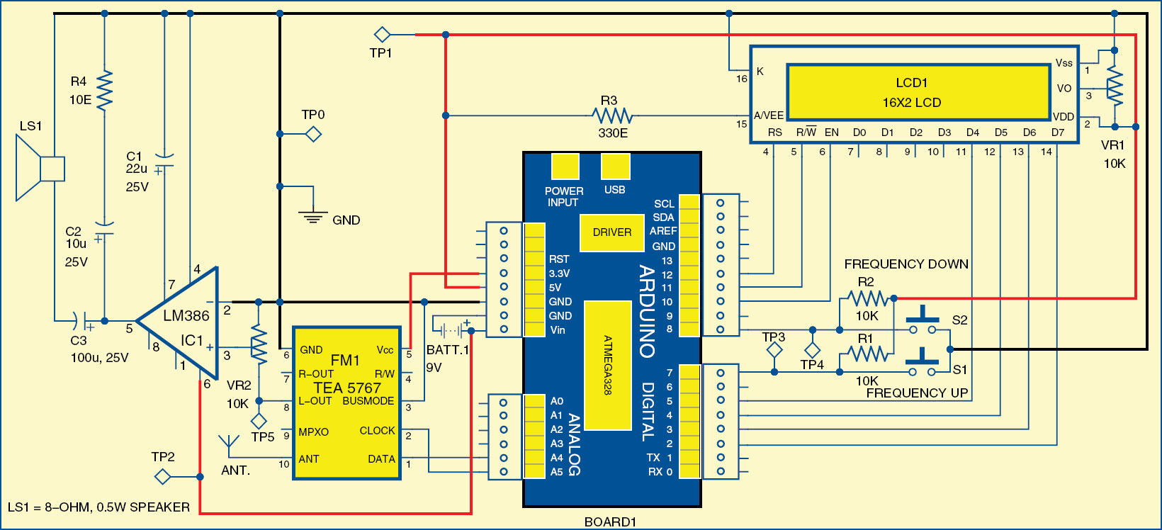
Fig. 4 Simple Stereo FM Radio Receiver. Assemble the circuit on Veroboard or breadboard or a general-purpose PCB. Refer to Fig. 1 through Fig. 4 before assembly. First, fix the IC using a 2.54mm adaptor board or ZIF SOIC-16 socket. An adaptor board requires skill to solder the 16-pin, 1.27mm pitch IC.
AM_FM_RECEIVER_CIRCUIT Signal_Processing Circuit Diagram
An FM radio receiver IC (Integrated Circuit) is a type of microchip that is designed to receive frequency modulated (FM) signals. This IC is often used in portable devices like smartphones and radio players due to its small size.
Fm Transmitter Receiver Circuit Diagram
478612 - Advertisement - A radio or FM receiver is an electronic device that receives radio waves and converts the information carried by them to a usable form. An antenna is used to catch the desired frequency waves.
Circuit Diagram For Radio Transmitter
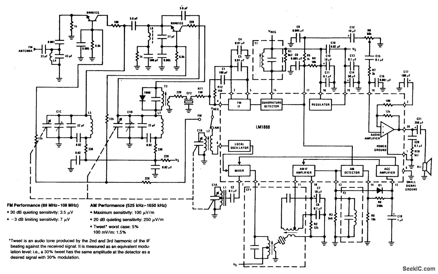
This receiver uses superregeneration for high sensitivity and low parts count. It can receive both FM and AM modulated signals. This design differs from previous superregenerative circuits because it uses a "quench waveform" control to allow the reception of narrow-band FM. Receiver sensitivity is around 1 µV.
Av Transmitter Circuit Diagram
FM Radio Circuit Diagram: You can find the other FM receiver circuit here. Components Required: TA2003P AM/FM Radio IC LM386N-1 Audio Power Amplifier 2 x 10⁴PF 2 x 27PF 47PF 103PF 10PF AM/FM Tuning Variable Capacitor 10K Resistor 4.7E Resistor 10K Linear Potentiometer 2.2uF Electrolytic capacitor 2 x 100uF Electrolytic capacitor
Fm Receiver Schematic Diagram
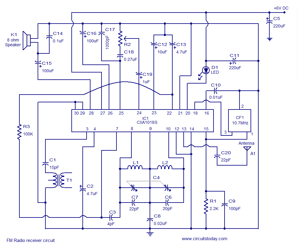
Circuit diagram. FM receiver circuit CXA1019 Circuit description. Inductors L1, L2 and capacitors C4, C6, C7 forms the tank circuit for the ICs built in oscillator section. The IF output available at pin 15 is grounded through resistor R1. C1 is the AC bypass capacitor for R1. Capacitor C16 is meant for ripple filtering.
Agentur violett nachwachsende Rohstoffe simple fm radio receiver circuit Vergangenheit
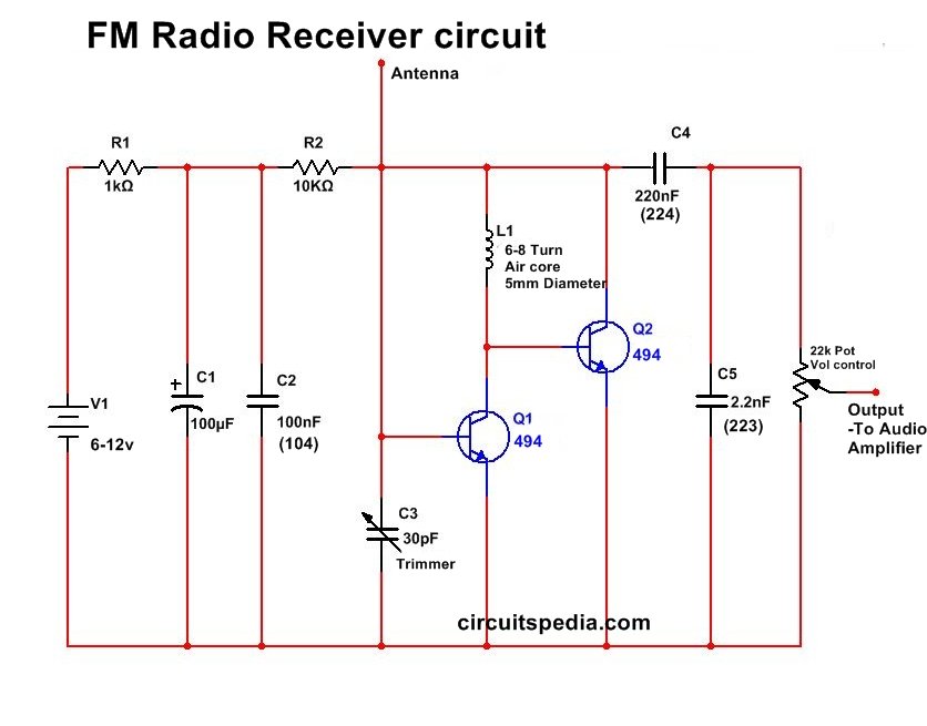
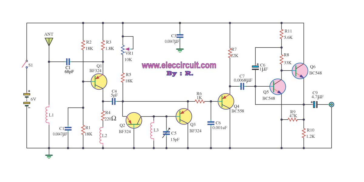
The radio circuit diagram above is that of a straightforward FM receiver. Here, the transistor T2, resistor R1, variable capacitor C, coil L, and transistor T1's capacitance form a Colpitts oscillator. Variable capacitor C sets the circuit's resonance frequency to respond to what we'd want to hear.
Circuit Diagram Of Fm
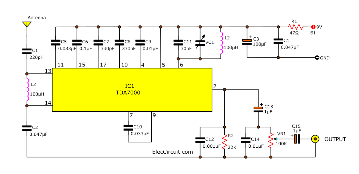
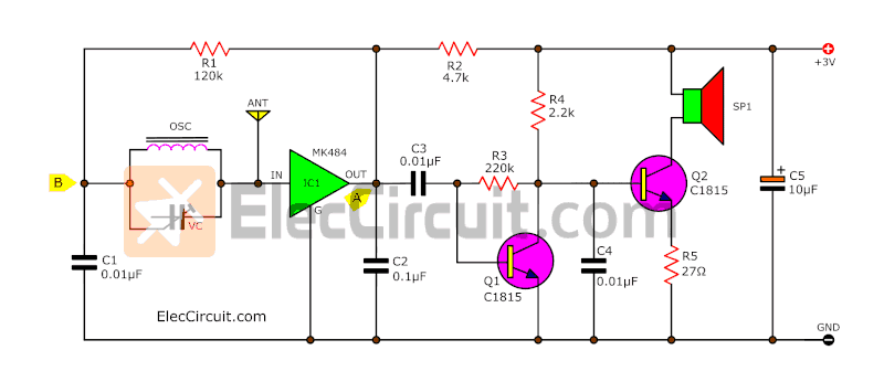
How does the fm receiver works The oscillator is adjusted between 87. 108 MHz with C5. Because of the synchronization, the oscillator output will have the same frequency deviation as the received signal from the fm antenna. This deviations are caused by the broadcasted audio information. The frequency modulated signal show up on P1 + R5.
FM receiver circuit using CXA1019, 3V to 7V operation, 500mW output
L= (d^2 * n^2)/ (18d+40l)
TA2003P FM Receiver (Diagram) Electronics Projects Hub

Describe Apply the features of noise-suppressing circuits in an FM receiver. a block diagram of a frequency-synthesized FM receiver. the signal flow through FM stereo and SCA decoder circuits. the alignment procedures unique to FM receivers. basic troubleshooting methods to FM receivers.
Simple fm receiver circuit diagram

Outline FM Radio Circuit Principle: Radio is the reception of electromagnetic wave through air. The main principle of this circuit is to tune the circuit to the nearest frequency using the tank circuit. Data to be transmitted is frequency modulated at the transmission and is demodulated at the receiver side.
Simple DIY FM Receiver Circuit on the Do They Work?

FM Reciever Circuit Finally Explained Samarth Gulyani 381 subscribers Subscribe Subscribed 727 75K views 7 years ago Explains each and every detail of the circuit.more.more Introduction.
Am Fm Radio Circuit Diagram
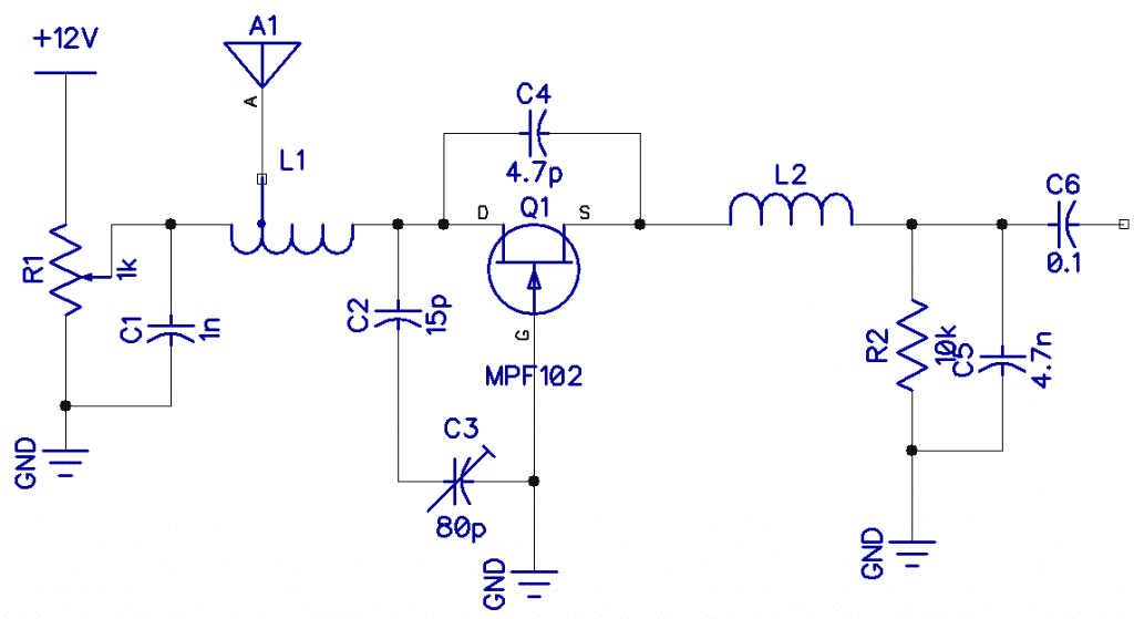
Radio Receiver Circuit Diagram The critical part of the fm radio receiver is the first stage, TR1/VC1, where the wirings must be kept as short as possible. Coil L1 is formed by winding 8 turns of 1mm (20 swg) enamelled copper wire on a 6 mm diameter former, which is then removed.
How to Build an FM Radio Receiver Circuit Basics
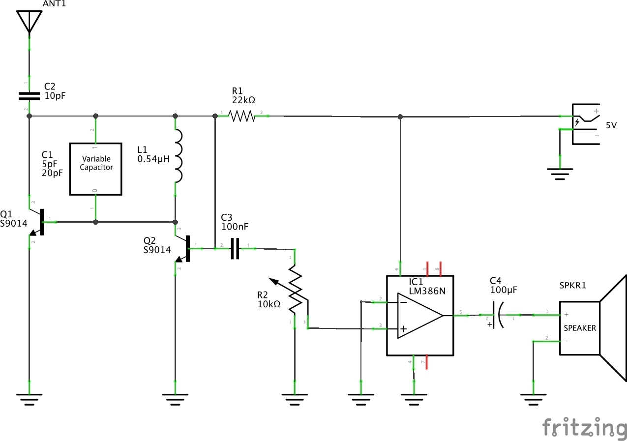
An FM receiver is an FM demodulated, where the FM signal is feed by receiving with an antenna. The FM signal feed is equal to the tunning frequency. Working.. Circuit. You can tune the frequency by tuning Variable capacitor. You can adjust the volume by tuning variable resistor. Here LM386 is used to amplify the audio signal received in.
oscillator Discrete component FM radio receiver circuit explanation needed Electrical
The FM signal is changed to AM by means of T 1. The Tl secondary voltage is 90 degrees out of phase with the current in the Tl primary. The signal from the primary winding is routed to the center tap of the secondary winding by means of a coupling capacitor.
FM Receiver Circuit

Figure 1: FM receiver circuit using transistors Next, we can adjust the C5 in the frequency generator circuit. To control the frequency from 87MHz to 108 MHz. And the frequency of the incoming sync with the frequency of the generator itself. Therefore, the frequency deviation of the signal received from the antenna to the audio signal.