How to select serializers and deserializers in HMI systems Analog
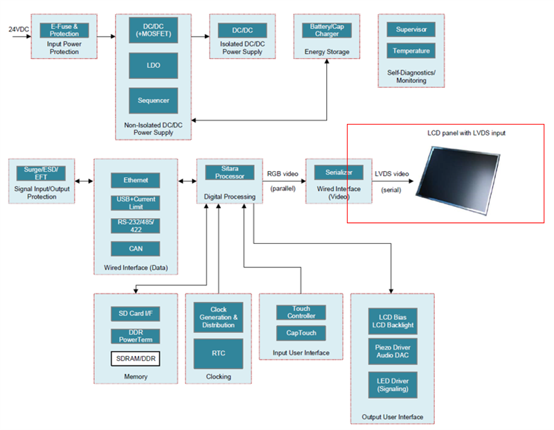
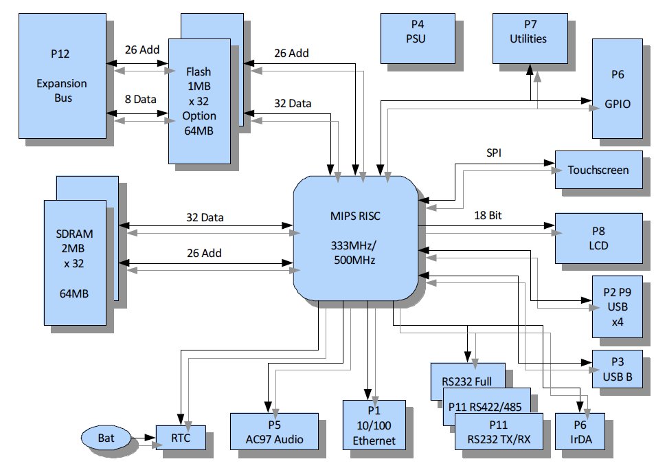
The HMI controller block diagram is an engineering development tool used to convey a complete product design using graphics. The block diagram also makes it easier to plan the breadboard for prototyping and testing of the HMI controller in a maker's workshop or laboratory bench.
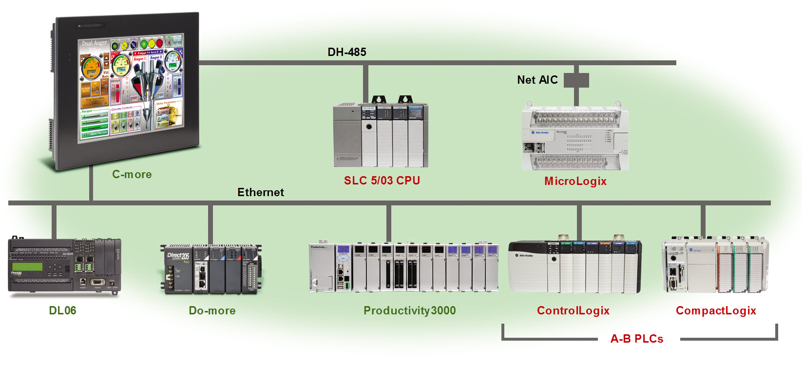
HMIs and MultiPlatform Communication
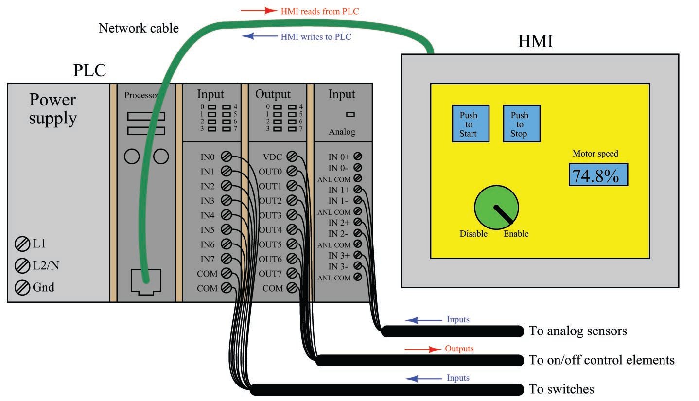
Modern HMI panels and software are almost exclusively tag-based, with each graphic object on the screen associated with at least one data tag name, which in turn is associated to data points (bits, or words) in the PLC by way of a tag name database file resident in the HMI.
New frontiers in automotive HMI and display design Embedded Computing
The Pulse Timer controller electrical wiring diagram. Image used courtesy of the author . The schematic and diagrams shown in Figures 6 and 7 reference the M5Stack Core and the relay module dry contact wired to the Arduino. Figure 7. The M5Stack Core-Pulse Timer controller electronic circuit schematic diagram. Image used courtesy of the author
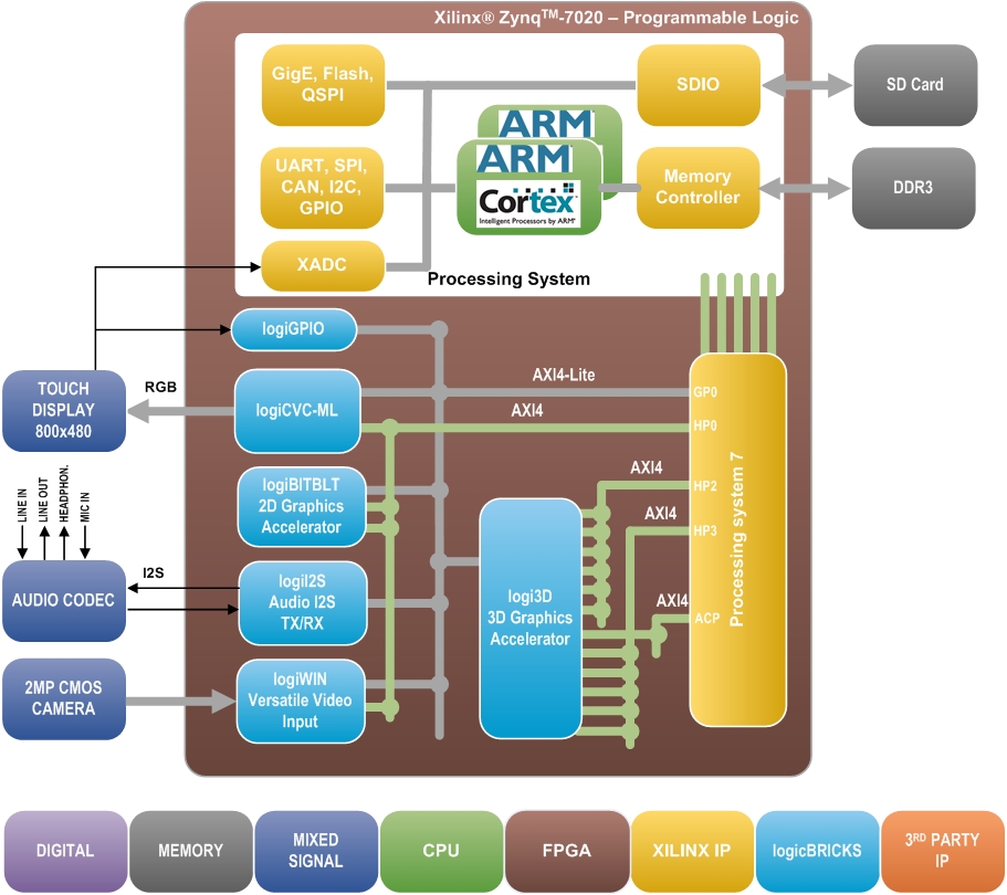
logiREFZHMIFMC Human Machine Interfaces for Xilinx Zynq7000 AP SoC
• HMI: A Human-Machine Interface (HMI) system's usability is determined by the its processing power, its ability to render complex and reality-like screens, its fast response time to user input and its flexibility to handle various levels of operator interactions.
Block diagram of a HumanMachine Interface (HMI) accident prevention

HMI controller block diagram is a tool engineers use when designing products. It helps to show the design with pictures. This makes planning for building and testing the HMI controller in a lab or workshop easier. Conclusion. A human-machine interface is a part of the SCADA system. Here we discussed what it is, its components, uses, trends, and.
Block diagram of automation packaging system proface remote HMI [8
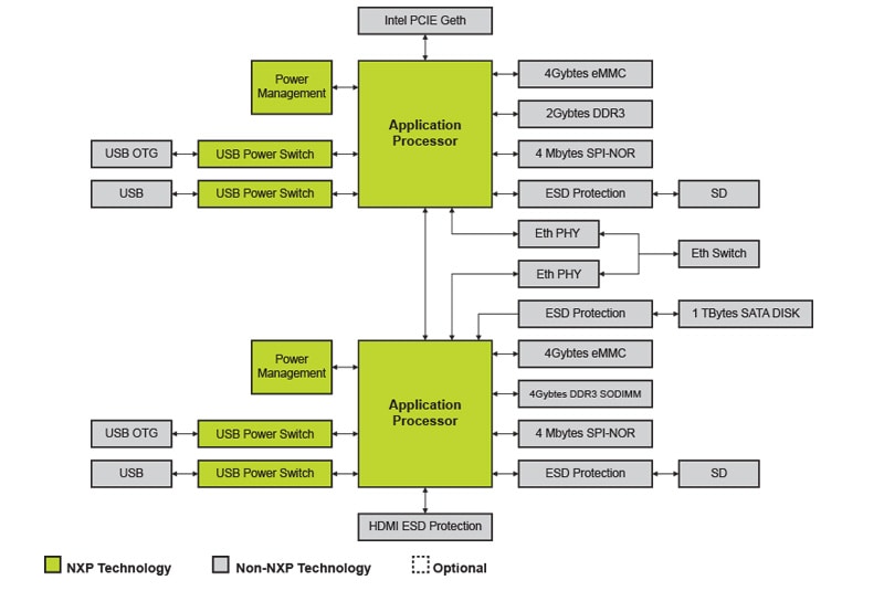
Last Updated: Dec 6, 2023 Powered by an industrial grade i.MX microprocessor, NXP provides HMI solutions for harsh industrial environments. These devices are power-on tested to emulate years of 24/7 operation for critical applications where accuracy, performance, and operational longevity are important factors.
Block Diagram of HMI SCADA System Download Scientific Diagram

1 power terminal block HMI Panel Diagram HMI Panel Front and Rear View 1 Screen Protection A plastic sheet attached to the HMI Panel screen for protection. Remove it during installation of the HMI Panel. 2 Audio Outlet Seal Prevents dust accumulation in the small outlet that serves the HMI panel's embedded speaker.
HumanMachine Interfaces (HMIs) Basics of Programmable Logic
View the TI HMI panel block diagram, product recommendations, reference designs and start designing.
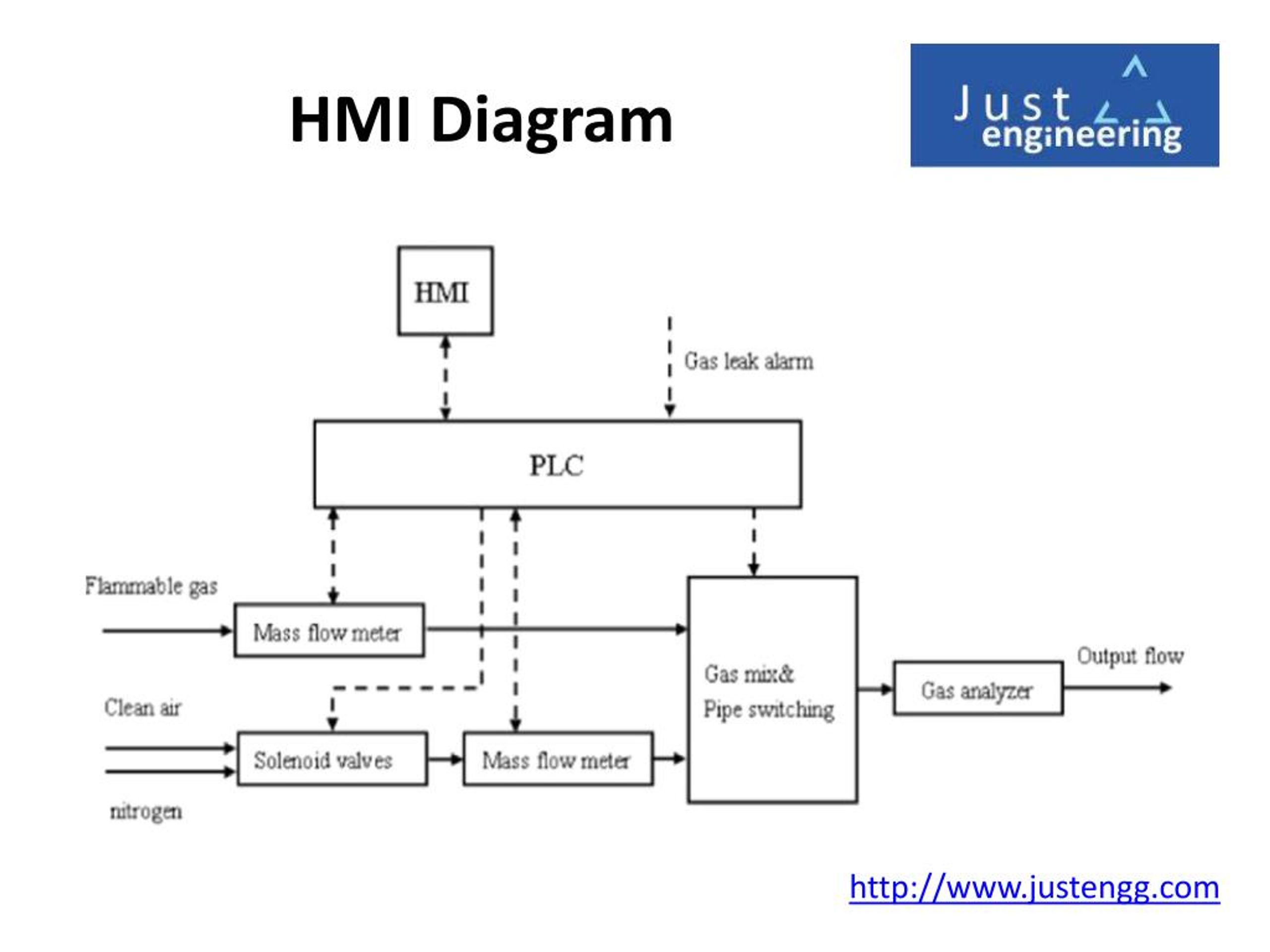
PPT Introduction to HMI (Human Machine Interface) Just Engineering
Abstract: Become well-versed with the tools available in the Siemens TIA toolbox and write PLC and HMI code effectively Key Features Find out how to use TIA Portal effectively to boost your productivity Learn about a structured design pattern and understand why it is so powerful when implemented correctly
Vision of the HMI platform block diagram. Download Scientific Diagram

Industrial HMI Last Updated: Dec 8, 2021 Powered by an industrial grade i.MX microprocessor, NXP provides HMI solutions for harsh industrial environments. These devices are power-on tested to emulate years of 24/7 operation for critical applications where accuracy, performance, and operational longevity are important factors.
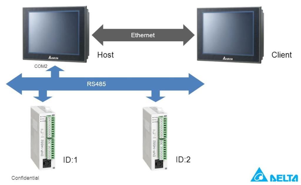
HMI PLC example Delta Industrial Automation
October 04, 2023 by Shawn Dietrich An overview of HMI data types, input controls, output indicators, and message functions, the building blocks used to construct informative and appealing HMI applications. Simply put, an HMI is the operator's portal into a control system.
Linuxready SBC targets HMI development
Chapter 1 4 HMI HANDBOOK Here are a few more benefits HMIs provide by interfacing seamlessly with a PLC-based control system: Line/Bar Graphs - Display real-time process values over time with line graphs or in easy-to-read bar graphs. Data Entry - Easily change process variables with a pop-up numeric keypad on the screen or with increment/ decrement arrows.
The structure of the developed HMI. Download Scientific Diagram

Download scientific diagram | Block diagram of automation packaging system pro-face remote HMI [8]. from publication: Implementation of Programmable Logic Controller in multi machine operations.
Texas Instruments Factory Automation & Control Solutions element14

HMI System Diagram How Does an HMI Work? HMIs are typically used in conjunction with a PLC (Programmable Logic Controller) to monitor and control processes in an automated system. In general terms, the HMI allows the user to communicate with the PLC via a graphical interface (typically a touchscreen).
Industrial HMI High tier NXP
The MEasy HMI block diagram is shown as below: The MEasy HMI uses D-Bus as the access interface for the QT application and the underlying hardware. MYIR provides a complete set of control and communication interfaces for RS232, RS485, CAN and LED and encapsulates the interface into a library for external use based on D-BUS Method and Signal.
Experimental setup block diagram. HMI humanmachine interface

HMI Block Diagram Posted on March 2, 2019 by Jan This diagram illustrate the HMI solution the way I am planning it. I would like one external RS485/UART so I can attach the display to any embedded solution. CAN, USB and SPI Backbone is mandatory. And I think SPI Half Duplex will do fine over max ca 50cm that we talk about here.