Simplified process flow diagram for pyrolysis. Process flowsheet also... Download Scientific

Simulation of Batch Slow Pyrolysis of Biomass Materials Using the Process-Flow-Diagram COCO Simulator by Chaiyot Tangsathitkulchai 1,*, Natthaya Punsuwan 2 and Piyarat Weerachanchai 3 1 School of Chemical Engineering, Institute of Engineering, Suranaree University of Technology, Nakhon Ratchasima 30000, Thailand 2
Schematic diagram of a plasma pyrolysis process for medical waste... Download Scientific Diagram

The conceptual process flow diagrams with integration of the anaerobic digestion and the pyrolysis processes are shown in Fig 1 and 2. The mass and energy balance for the process with the.
Pyrolysis system used to prepare biochar Download Scientific Diagram

Flow chart of the process of plastic waste pyrolysis. Depending upon the working conditions such as. and Fig. 6 shows the schematic flow chart of slow pyrolysis method. Slow pyrolysis of plastic waste involves a heating rate of 0.1 ∼ 1 °C/s [24], and it has a number of advantages over fast pyrolysis, including better.
Process flow diagram of a freefall reactor for the pyrolysis of... Download Scientific Diagram

Process flow diagram of pyrolysis plasma reactor [23]. Source publication +24 A review on the pyrolysis of woody biomass to bio-oil: Focus on kinetic models Article Full-text available Dec 2015.
Pyrolysis process flow diagram. (adapted from [10], [11] ) Download Scientific Diagram

Simplified flow diagram for typical pyrolysis unit. (a) Biochar and bio‐oil production.. Pyrolysis process emits mainly methane, hydrogen, carbon monoxide and carbon dioxide. The organic materials present in the biomass substrate starts to decompose around 350-550°C and it can proceed until 700-800°C without the presence of air.
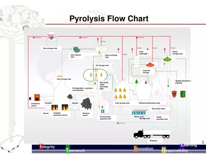
PPT Pyrolysis Flow Chart PowerPoint Presentation, free download ID4726571
Pyrolysis is the key process in carbon nanomaterial synthesis [ 1-4 ], bulk carbon production [ 5, 6 ], fabrication of carbon-based devices [ 7-10 ], fuel generation from organic waste [ 11-13] and molecule fragmentation for their analysis via gas chromatography-mass spectroscopy (GC-MS) [ 14-16 ].
The schematic diagram of the pyrolysis system Download Scientific Diagram

Flow diagram of pyrolysis plant used for fuel-gas production. Flow numbers are used in energy balance analyses described in Table 8.. W. Kaminsky, The Hamburg fluidized-bed pyrolysis process to recycle polymer wastes and tires, in: J. Scheirs, W. Kaminsky (editors), Feedstock recycling and pyrolysis of waste plastics: converting.
Process Flow Diagram of a classical pyrolysis plant with a novel vortex... Download Scientific

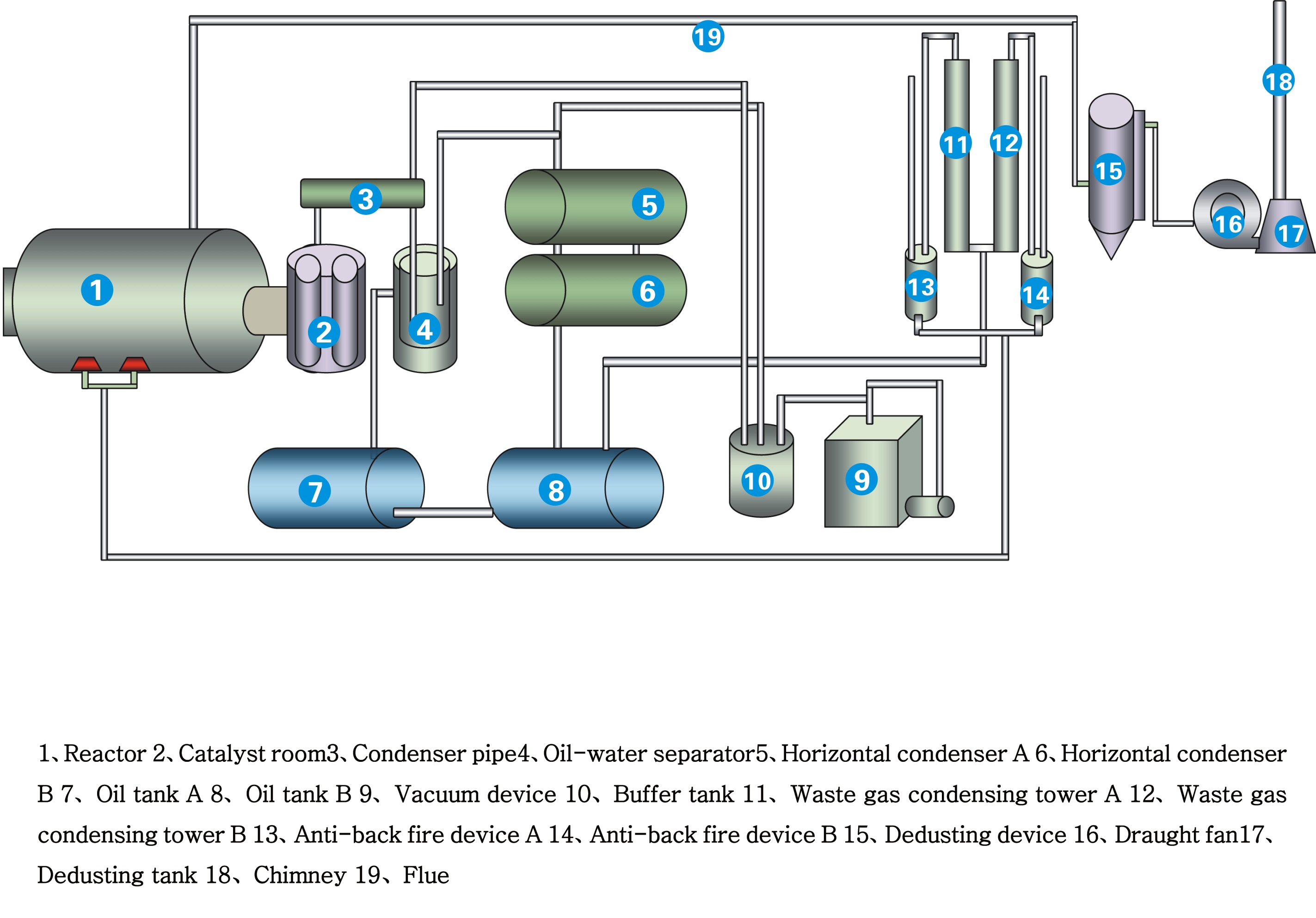
The process in a fixed-bed pyrolysis reactor is shown in form of a flow diagram in figure 1. Zoom In Zoom Out Reset image size Figure 1. Process in a fixed-bed pyrolysis reactor.. The discharge pipe is a channel for conveying the pyrolytic fuel which leaves the reactor during the pyrolysis process. It was constructed from a pipe.
Representative process flow diagram for the fast pyrolysis of... Download Scientific Diagram

The Process Flow Diagram (PFD) for a typical pyrolysis process is shown in Fig.. View in full-text Context 2. recent TGA analysis [56] [57] [58], an overall kinetic model of.
Pyrolysis
 Simplified Process Flow Diagram.jpg)
Pyrolysis Process Flow Diagram [14] Source publication Waste-to-Energy (WTE) Technology Applications for Municipal Solid Waste (MSW) Treatment in the Urban Environment. Article Full-text.
Pyrolysis Plant Pyrolysis Plant to Process Plastic Biomass tyres into liquid diesel petrol fuel
Jan 2022 Dipali Gahane Divyajyoti Biswal Sachin Arvind Mandavgane Biomass, a renewable source of bio-energy, making it a promising solution for reducing greenhouse gas (GHG) emissions. Biomass is.
General layout of pyrolysis process. Download Scientific Diagram

Pyrolysis is a promising process to convert the biomass into bio-oil. This study reviewed the progress in pyrolysis in terms of the reaction, process, pyrolysers, main parameters and the status of commercialisation of pyrolysis. Keywords At the beginning of the 20th century, crude petroleum fuels covered only 4% of the world's energy demand.
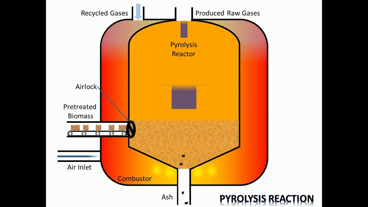
Process of Pyrolysis YouTube
A step by step overview of the tyre pyrolysis process The following steps broadly describe the tyre pyrolysis process: 1. Pre-treatment: Pre-treatment usually involves extracting the steel and fibre reinforcement of the tyre before, or during, shredding, chipping or cutting the tyre into smaller pieces. This may involve a two or three step process.
Pyrolysis process diagram ([18], p.4) Download Scientific Diagram

2.1.1. Functional Specification 6 2.1.2. Develop a Process Flow Diagram and Mass and Energy Balances.. 9 2.1.3. Process and Instrumentation Diagram (PID) 12 2.1.4. HAZOP Methodology 12
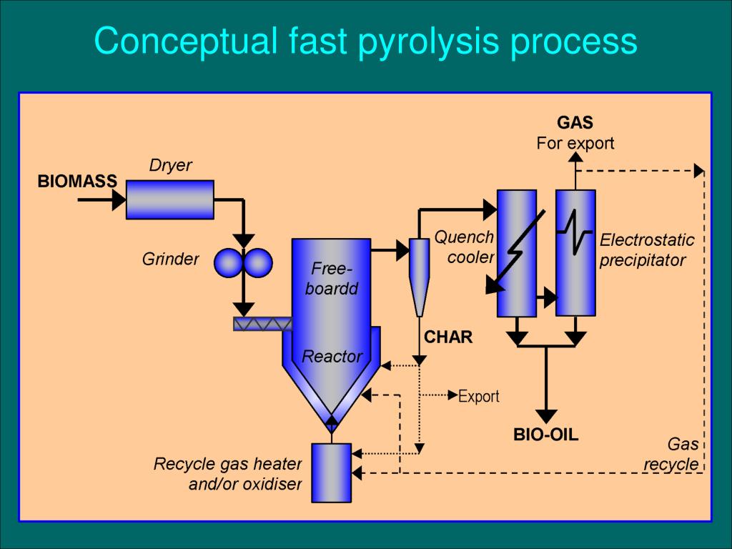
PPT Conceptual fast pyrolysis process PowerPoint Presentation, free download ID439544
Going up in flames: The pyrolysis of polyethylene waste plastic is studied by thermogravimetric analysis (TGA) and in a fluidized-bed reactor.A kinetic model consisting of two parallel first-order random scission steps is proposed on the basis of the TGA study. The gas- and liquid-phase pyrolysis products from the fluidized-bed reactor are potential precursors for the production of fuels and.
Flow chart of a fluidised bed pyrolysis process. Download Scientific Diagram

1 Altmetric Explore all metrics Abstract Biomass is a renewable source of bioenergy, making it a promising solution for reducing greenhouse gas (GHG) emissions. Biomass is converted into bioenergy by the thermochemical and biological routes. Among all thermochemical conversion processes, pyrolysis is the most popular due to its ease of operation.