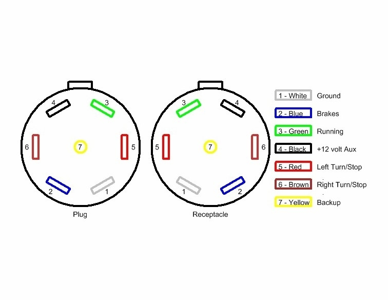
7 Way Trailer Plug Wiring Diagram Wiring Diagram
To wire a 115V plug, follow these steps: Ensure that the power source is turned off and unplugged. Identify the hot, neutral, and ground wires on your 115V appliance or device. Strip the insulation off the ends of each wire to expose the bare copper. Insert the hot wire into the brass terminal screw on the plug.
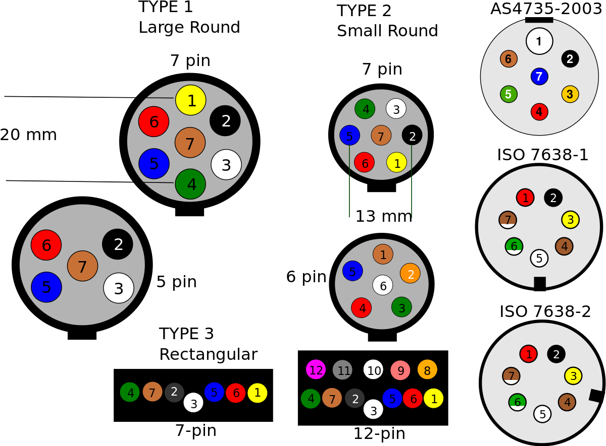
Wiring Diagram For 7 Prong Trailer Plug Trailer Wiring Diagram

Connect the white wire to the chrome screw and the ground wire to the green one in the same way. Give the cord a good tug to make sure everything is secure before you reassemble the plug casing and tighten the cable clamp, if there is one. Advertisement. If the 3-prong plug on an appliance has broken — don't panic. You can actually replace it.
Plug Diagram Us How to wire a French electric plug CEE 7/6 YouTube

Download Article. 1. Remove 1 ft (30 cm) of the outer coating of the 10/4 cable. Clamp a wire stripper around the outlet end of the 10/4 cable so it's 1 foot (30 cm) from the end. Pull the wire stripper toward the end of the cable to cut through the outer coating and expose the wires inside.
Electrical Wiring/Vanity
Attach the Wire to the Screw. Fit the hook of each wire over the appropriate screw terminal so that the end of the wire is on the right side of the screw. The wire insulation should be close to (but not under) the screw; only the bare metal of the wire should contact any part of the screw. The Spruce / Kevin Norris.
220v Welder Plug Wiring Diagram Free Wiring Diagram

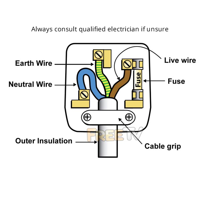
1. Strip the end of the thick cable coming from the appliance into the plug, using wire strippers. Take off roughly 3 centimeter (1.2 in) of white covering, leaving you with three thinner cables. [1] 2. Undo the Philips screw in the center of the plug, on the side with the three pins poking out. 3.
White 3 Pin Plug (13 Amp) For Sale Online in Ireland Shop Now
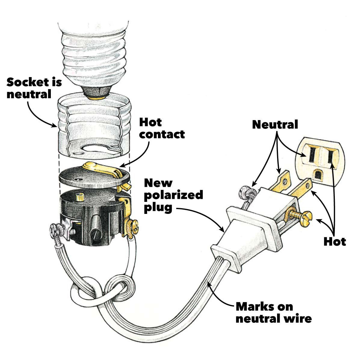
Step 1: Cut the Old Plug and Slice the Jacket. Step 1. First, cut off the damaged plug. Then use a utility knife to split and slice off the jacket about 3/4 inch from the end of the cord. Take care not to cut the three wires inside. Using a wire stripper, as shown, strip 1/2 inch of insulation from the end of each wire.
Lt1 Spark Plug Wire Diagram

In this video we'll show you how to wire a removable grounded plug ends, both the black and white. These plug ends have a 2 part construction, the housing a.
7 Pin Trailer Plug Wiring Diagram Wiring Diagram
a basic explanation of the wiring of an electrical receptacle (plug-in), so you'll know what to do when replacing one
How To Wire A 3 Pin Plug Mmk Electricians Dublin Wiring A Plug
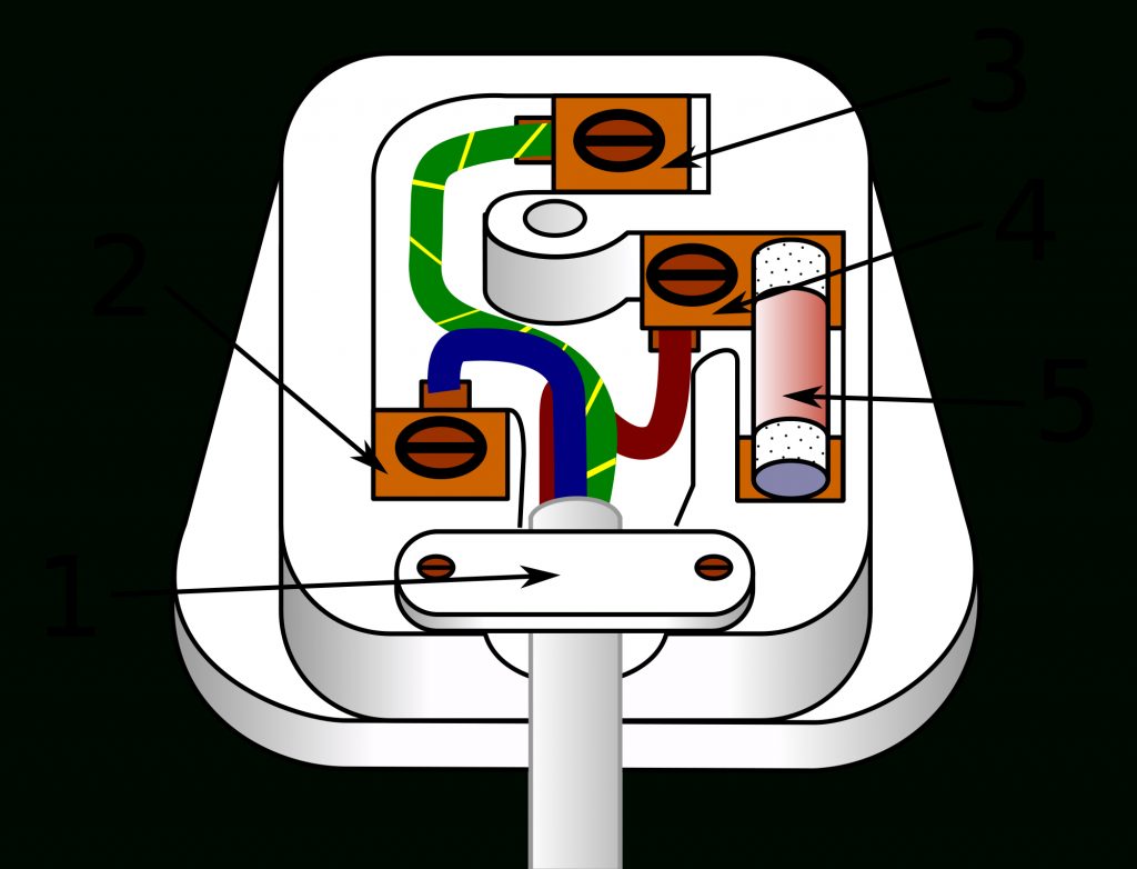
It can be confusing trying to figure out what color wire goes on a three prong plug. There are three types of wires in a plug: the black, the white, and the green. The black wire is the hot wire, which carries electricity; the white and green are neutral and ground. The green wire goes to the ground screw. Using the wrong wire can damage your.
6 Wire Plug Trailer Wiring Diagram Trailer Wiring Diagram

How to wire a plug - Step 1. Step 1: The first step of rewiring a plug is to cut back the outer sheath (black) of the flexible cable, to get access to the coloured wires underneath; give yourself plenty of wire to work with. Line them up on the diagram of the plug so you can see the lengths to cut. There are three coloured wires inside the.
50 Amp Rv Plug Wiring Schematic Free Wiring Diagram

Wiring a plug diagram is a crucial aspect of electrical work and is an essential skill for homeowners, DIY enthusiasts, and professionals alike. Understanding how to correctly wire a plug can prevent electrical hazards and ensure the efficient functioning of electrical appliances. The diagram provides a visual representation of the various.
30 Amp Plug Wiring Diagram Printable Form, Templates and Letter
Connect the red and black wires to the line wires of the plug (Fig 2). The white neutral wire is then connected to the middle terminal or the neutral wire (Fig 2). Then connect the green ground wire to the unit's ground shell (Fig 2). Make sure the nuts are securely fastened. Plug in and replace the cover.
Wiring A Trailer & Plug Commercial Trailers Qld Aluminium Machine

All three of these wires need to be attached to the receptacle. Step 2 - Attaching wire to the electrical receptacle. The first this to do is attach the bare wire to the back of the electrical box (wrap around one of the screws) but leave enough of a "tail" to attach the the green or blackish screw at the bottom of the plug.
Vera Wiring Trailer Wiring Diagram 4 Pin Flat

Strip the wires: Use a wire stripper to remove the insulation from the end of each wire, exposing about 1/2 inch of bare wire. Insert the wires into the plug: Refer to the wiring diagram for the specific plug you are using. Typically, the hot wire goes to the brass terminal, the neutral wire goes to the silver terminal, and the ground wire goes.
Schematic 7 Way Round Trailer Plug Wiring Diagram

Crimp the ring lugs on each of the three wires individually. Push the wire through the barrel of the ring lug until the end of the wire is just past the end of the barrel. You don't want to push it too far or it will interfere with tightening the screw down. Then place your wire crimpers around the barrel and squeeze.
39 Reese 7 Pin Wiring Diagram Wiring Diagram Online Source

Wiring a Grounded Duplex Receptacle Outlet. This is a standard 15 amp, 120 volt wall receptacle outlet wiring diagram. This is a polarized device. The long slot on the left is the neutral contact and the short slot is the hot contact. A grounded contact at the bottom, center is crescent shaped. Don't use this receptacle when no ground wire is.